About this deal
In this section we’ll install the wiringPi library on the Raspberry Pi, connect up a single LED, and write a simple program in C to make it flash. As I said in the intro, we’re going to use the wiringPi library to talk to the GPIO pins on the Raspberry Pi. It was written by Gordon Henderson and I have been so impressed with its ease of installation and use. Web designed exclusively for the toyota tundra, this is the world's first digitally controlled light bar designed for a specific vehicle. The new vs old and install. 20142018 Toyota Tundra Hood Grille Knight Rider NSV LED Light Bar Kit Then test the 555 timer oscillator by connecting an LED in series with a resistor on the output. With the values chosen above, your LED should blink about 3 times per second.
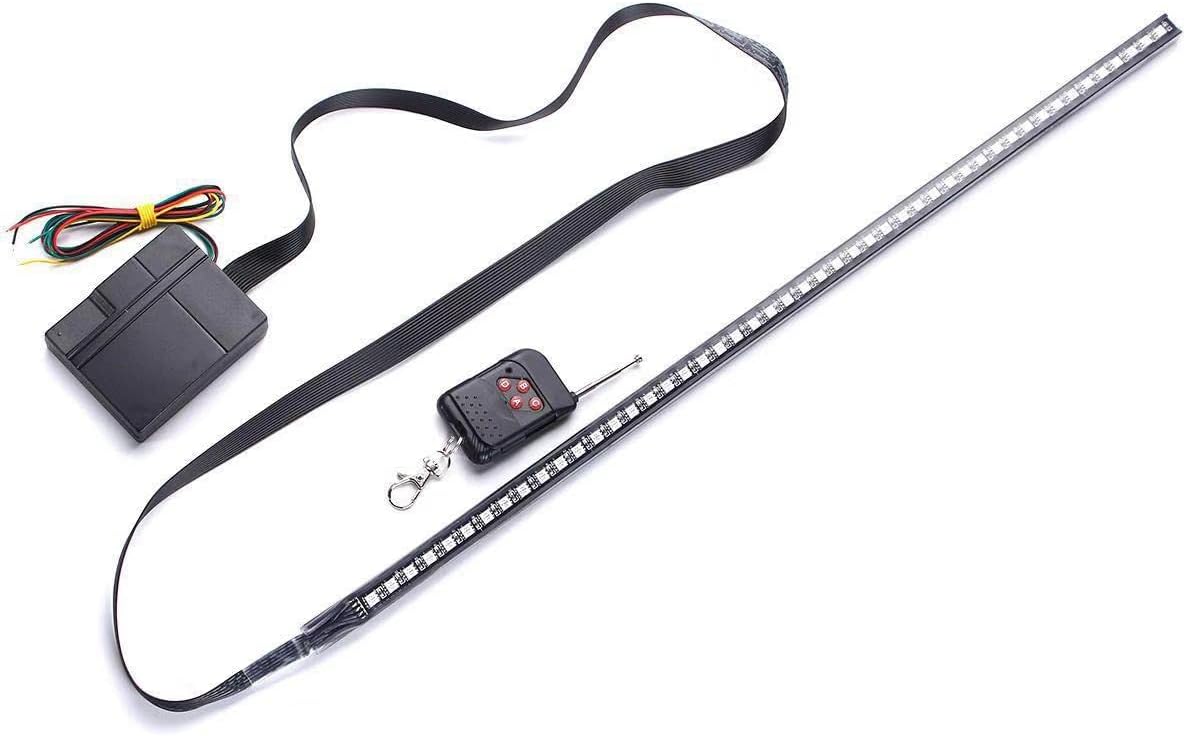
The new vs old and install. Web added the nsv led night rider light bar hi any advise.after installing the nsv light bar.i notice when i put my left turn signal on the drl flash with the turn. Web designed exclusively for the toyota tundra, this is the world’s first digitally controlled light bar designed for a specific vehicle. Web In The Following Videos, We’ll Show You How To Install The Nsv Led Light Bar In The Toyota Tundra.I shouldn’t need to tell you any more about the Pi and power adapter – I’m assuming you’ve either got one already or are thinking about buying one. Onto the components: This is the first part of a two parter on creating the K.I.T.T. light bar with LEDs using your Pi (I know, awesome, right?).
To install git (code repository) and then wiringPi, type the following commands: sudo apt-get install git The counter starts at 0 and increases every time it gets a pulse on its counter input. The Oscillator I usually like to build the circuit on a breadboard first. Just to make sure I understand it and am able to build it before soldering it onto a prototyping board. Once the circuit is soldered, it’s a little bit harder to make changes if you messed something up. (But not too hard though, you can always desolder). Step 1: Building the oscillator
More Circuits & Projects Tutorials
The number of bands (3,4,5 or 6), indicates their tolerance (more bands is generally higher precision). In wiring terms, we connect the GPIO 17 to an inner row (row 57) on the breadboard (via the brown wire). The inner rows are connected by metal strips underneath the cover (but not the inner columns). When you plug something into a row, the circuit will continue to any other item that is also plugged into that row. In our case the circuit will find an LED. Web nsv is a world leader in led lighting technology, specifically led daytime running lights. We provide toyota tacoma light bar grille, nsv led light bar for the. We have designed and developed led lighting systems for toyota, gm, nissan, mazda. Web Hidnation.com Is Dedicated To Offer You The Best When It Comes To Quality Led Light Bars. First of all, the bands. The colours represent numbers – this is just easier than printing teeny, tiny font on them. There are lots of online calculators and explanations for the colours, so I’ll leave that up to you to read about later.
In essence all you need to do is ask for 330 ohm resistors, but the info above will help you if you are given blue ones or brown ones and you don’t want to feel like an idiot for asking what the difference is (like I did – I knew I should have paid more attention when I was little and my Dad was fixing the telly). There are only 6 LEDs, but 10 counter outputs. Each of the LEDs on the two sides connect to output 0 and output 9 as shown in the knight rider circuit diagram above.
The frequency equals the number of pulses per second. How To Build The Knight Rider Light Bar With LEDs? This is the list of items you’ll need. If you want clarification on any of these (buying electrical components is a bit of a leap in the dark the first time you do it), have a look at the pictures and further info below. If you’re pretty familiar with these things, then grab the list, skip the details and move onto Step 2. Note that for this first step, the wiring on the Pi is the same for revision 1 and 2 boards. Step 4 – Run Your Code
LEDs only work in one direction. Ensure the longer leg (the positive, or anode) is on the same row as the wire coming from GPIO 17. You don’t need a keyboard or monitor for this tutorial – if your Pi is on the network you can log in via ssh and do everything from a terminal.A breadboard is a way to create electrical circuits without having to use a soldering iron. Very handy. You can get them in shops (like Maplin in the UK) that sell electrical components, or buy them online. They come in various sizes. I’m using a “full size” board, with two power buses (the outer columns), 63 rows, and 10 inner columns. You can use a half size board – as long as it has at least 31 rows you won’t need to change the wiring in this tutorial. My breadboard looks like this: This guide is for complete beginners, so I’ll be talking through all the parts and the entire process step by step.
Related:
 Great Deal